Module dock
The dock is the interface between a half and a module: 8 contacts on each side, carrying power in both directions, a UART, a boot line and an enable, held together by magnets. This page covers the mechanics, the net names on both sides, what flows through the dock and what does not (USB data), how the half identifies a docked module, and how module firmware reaches a module. The one thing to know: no dock contact carries USB data, and the pin-to-signal order is not established, so do not probe the contacts with a supply.
At a glance
- 8 contacts on each side: spring pins on the half, flat pads on the module.
- Net names: UART (
TX/RX), boot select, module battery, 5 V feed, enable, ground; noD+/D-. - Power flows both ways: the half charges the module on USB, the module powers the half off USB.
- A docked module's address encodes type and side: Touch
0x10/0x11, Track0x20/0x21, Tune0x40/0x41;0xF0/0xF1means nothing booted answers. - Each half's bay holds 6 magnets (measured).
Mechanics
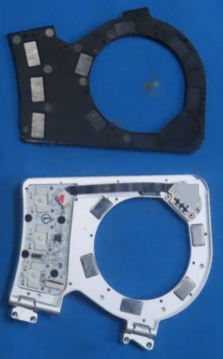
Each half has one module bay: a circular through-cutout in the dock section with one straight chord,
where the contacts sit DOC CRR EP p2, p323. The half side has an 8-position spring-pin
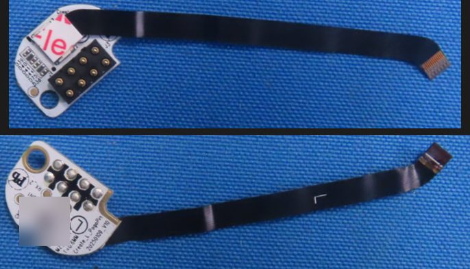
(pogo) block: 8 gold domed pins in two staggered rows of four, a black insulator, through-hole, with no
maker marking visible anywhere in the filings DOC CRL IP2 p15; CRR IP2 p1312. The pins
are on a small D-shaped pogo board (Create_L_PogoPin_20250109_V10, 0.6 mm, about 16 x 17 mm) with 5-6
small ESD diodes, joined to the dock (thumb-key) board by a black flex of about 50 mm DOC INFERRED.
Magnets. Each half's bay holds 6 magnets: one on either side of the contact block and 4 spaced around the bay MEASURED (owner's board, paper-clip test, 2026-09-23). In the photos they are the two small light-colored features flanking the contact block on the chord (the manual drawing shows a small pocket on each side of the pins) and the 4 blocks on the carrier plate; the 5 blocks on the metal bay bracket did not attract a clip, so they are not magnets MEASURED DOC INFERRED13. Each module base holds 6 metal blocks, magnet or steel not tested; the manual says there are magnets "in the dock and on the bottom of the module" DOC3 (details).
Docking. Align the contacts, let the magnets pull the module in and seat it completely flat "for a proper connection with the data pins"; to remove it, push up through the dock cutout with the keyboard lifted or tented DOC345.
Design history. The vendor's dock design of late 2023: pogo pins plus magnets strong enough to hold a module when tented, stabilizing pins against sideways movement and contact wear, and a dock base enlarged from 66 to 69 mm across, 4 mm high; prototype pogo pins went from a 45-degree to a vertical arrangement DOC1011. A Naya patent on the Float describes a teardrop-shaped indent in the dock and a matching protrusion on the module to stop rotation, and a variant with a ferromagnetic base; it describes no contacts or data interface DOC13.
The contact blocks
| Side | Board | Contacts | Labels as read | Evidence |
|---|---|---|---|---|
| Half | pogo board Create_L_PogoPin_20250109_V10 |
8 spring pins, two staggered rows of four | pads (left back) GND_4, BOOT_2, MZ_VBAT, RX_2, ..._ON1; (right) GND_4, BOOT_2, 5V_1, RX_2, TX, USB_5V |
DOC CRL IP2 p15; CRR IP2 p13 |
| Half | dock board and mainboard | (nets toward the pogo board) | dock board TX_1, RX_1, BOOT_1, MZ_VBAT_1, LDO_ON_1, USB_5V_2; mainboard LDO_ON, TX, RX, POGOPIN_5V |
DOC CRL IP1 p9; CRL IP2 p16; CRR IP1 p12 |
| Tune | main board J5, plus 8 flat pads on its base |
8, in a 1-2-2-2-1 stagger | GND, VBAT, RX, ON, GND, TX, a 5 V line, BOOT1 |
DOC CRL IP3 p19; CRL IP2 p17-p18 |
| Touch | pogo board J2 |
8 domed contacts in two columns of four | GND, VBAT, RX, …ON, BOO…, GND |
DOC CRL IP5 p32 |
| Track | Track_Pogo_Pin_20241122_V08, fed through a separate interposer |
8 in a 2 x 4 block | GND, VBAT, RX, ON; interposer headers GND, RX, TX and ON, 5V, GND, plus a BOOT1 pad |
DOC CRL IP6 p37, p40 |
All citations12. Some earlier readings counted 12 contacts on the Tune and 10 on the Touch and Track; every board has 8 DOC. The Touch base shows only a single row of 4 contacts through a slot, although its pogo board has 8; why is not known. Vendor underside renders showing 6 pads in a row are older marketing art DOC114 (details).
What the dock carries
The net set is: UART (TX/RX), a boot-select line (BOOT/BOOT1), the module battery line
(MZ_VBAT/VBAT), a 5 V feed (USB_5V/POGOPIN_5V/5V), an enable (LDO_ON/MODULE_ON/ON) and
ground. No contact label anywhere reads D+ or D- DOC1. The functions follow from the names
only; which pin carries which net, and the direction of each line, are not established, because the
schematic is confidential INFERRED (details).
The module boards' VBUS, VBUS_5V and USB_5V pads carry the 5 V feed from the dock, not USB data.
The modules' STM32F411 has a USB device, but nothing shows it wired to the dock DOC INFERRED.
| Net (by name) | Half side | Module side | Direction (inferred) |
|---|---|---|---|
| UART | TX, RX (TX_1, RX_1, RX_2) |
TX, RX |
both, one each way |
| Boot select | BOOT_1, BOOT_2 |
BOOT1 |
half to module |
| Module battery | MZ_VBAT, MZ_VBAT_1 |
VBAT |
both |
| 5 V feed | USB_5V, POGOPIN_5V, 5V_1 |
5V, VBUS, USB_5V |
half to module |
| Enable | LDO_ON, ..._ON1 (MODULE_ON on the mainboard) |
ON |
half to module |
| Ground | GND_4, GND3 |
GND |
- |
Pin positions are not established OPEN.
Power flows both ways through the dock: the half feeds 5 V to a docked module (which charges it when
the keyboard has power), and a charged module powers the half when there is no USB DOC34.
On each module the dock 5 V and the Qi receiver
output (QI_VBUS) reach the SGM41523 charger through SL Schottky diodes; the Tune and Touch also
carry an SGM62117 buck-boost, whose role (3.3 V from the cell, or 5 V toward the dock) is not established
DOC INFERRED1. The modules have no radio and link to the half only through the dock contacts; the Qi
coil is a power receiver DOC1.
A January 2024 vendor update described a wired full-duplex chain at "10 mb/s" from the right module through both halves and the left module to the computer; the dock link's actual rate on shipped hardware is not known, and no wired traffic between the halves has been observed DOC INFERRED12 (details); see Split link.
What the host sees
Docking or undocking a module makes that half re-enumerate on USB; an open serial handle goes stale and must be reopened. NayaFlow restarts itself when a module is re-docked MEASURED (owner's board, 3.41.0, 2026-09).
A docked module's type and side come from its dock address: bit 0 is the side (0 left, 1 right) and the high nibble is a one-hot type MEASURED (owner's board, 3.41.0, 2026-09-03; a second board, 3.28.7, 2026-09-19; also on the nayactl maintainer's board, 3.30.18):
| Module | Left | Right | Evidence |
|---|---|---|---|
| Touch | 0x10 |
0x11 |
MEASURED |
| Track | 0x20 |
0x21 |
MEASURED |
| Tune | 0x40 |
0x41 |
MEASURED |
| Float (never shipped) | 0x80 |
0x81 |
INFERRED by the pattern; nayactl placeholder7 |
| nothing booted answers | 0xF0 |
0xF1 |
MEASURED |
A docked module that has not booted (at about 0-1 % battery) stays dark and answers as 0xF0 (left) or
0xF1 (right), reporting firmware 0.0.0; an empty dock gives the same reply MEASURED (a second board,
3.28.7, 2026-09-19; the no-answer value on 3.41.0, 2026-09-03). The nayactl maintainer reports that the
module boots once it has drawn enough dock power, at about 1 % REPORTED8.
- Presence. The presence command (
de/1002) reports presence only (01for any module); reading it as a type code labels every module a Touch MEASURED (owner's board, 3.41.0)8. - Handshake.
de/1001replies00 01 <addr>for a docked, booted module (status00, handshake byte01, dock address) and00 00 f0when nothing booted answers MEASURED. - Which bay. Use the dock address, not which LEDs look lit, to tell which bay a module is in MEASURED (a second board, 3.28.7, 2026-09-19).
- Per half. Module queries go to the half the module is docked on, and each half reports only its own module MEASURED.
- Module firmware.
de/1008answers on both halves: reply00 <addr> <flag> 00 <major> <minor> <patch>(the flag byte read00, and01with an all-zero version while a module had not reported yet) MEASURED (owner's board, 3.41.0, both halves, 2026-09-11 and 2026-09-16; also reported in nayactl pull request 5,00 20 00 00 02 02 02Track left and00 11 00 00 02 02 02Touch right on the maintainer's 3.30.1 board9). - Versions in the field. The Tune and Track on the owner's 3.41.0 board report module firmware 2.3.3, while the Touch on the same board reported 2.1.2 (right-docked, 2026-09-11 and 2026-09-16); 2.1.2 (also on a second board's modules) and 2.2.2 are in the field too MEASURED9.
- Stored bundle. The stored module-bundle version (
de/100a) is answered by the left half only, because only the left half holds the module firmware store MEASURED (owner's board, 3.41.0, 2026-09-16).
Byte strings follow the convention on Transport; the commands are on Modules.
Configuration and lighting belong to the bay
Module configurations for both bays live on the left half; NayaFlow writes even the right-docked
module's configuration to the left, and the right half reports no module-config slots MEASURED (owner's
board, 3.41.0, NayaFlow write captures, 2026-09). Each layer's keymap has 8 bay positions
(0x4A-0x51: Touch, Track, Tune, Float, each left and right) that point to a module-config slot,
inherit from the base layer, or are empty; a module whose bay is empty on the base layer runs its own
animation and answers no gesture MEASURED (2026-09-03, 2026-09-16). See Keymap.
Each bay has its own 24-entry LED block in the whole-board map (88-111 left, 112-135 right); the block belongs to the bay, not to the module: swapping a Tune and a Track kept each side's color MEASURED (owner's board, 3.41.0, 2026-09-08). See Layout and positions.
Module firmware through the dock
Module firmware reaches a module through the dock. NayaCore carries a 1 MiB LittleFS bundle
(FlashMemory.bin) of encrypted module apps (.sfb files) inside its own executable, uploads it to the
LEFT half's module store over the bootloader's serial protocol (image slot 4), then tells the half to
program the docked module (de/1005) STATIC6. We have run it on the owner's board (left half on
3.41.0, 2026-09-23): NayaFlow updated a Touch, and OpenFlow's own module update then flashed a Touch up,
down and up again and downgraded a Track, which read back as a correct Track; de/1005 carries one byte for the
module type (01 Touch, 02 Tune, 03 Track). One later Track update never finished and left that
Track silent MEASURED15. See Module firmware.
The UART and BOOT1 nets fit a module update driven by the half over UART with a boot strap
(inferred, untested); nothing shows the STM32's USB bootloader reachable through the dock INFERRED. Module
images are not MCUboot images; the module's own bootloader is unidentified (NayaCore does name an
M_MCUBOOT_RESTART module mode) STATIC6.
Vendor rules for a module update: only one up-to-date left half with the module docked may be connected, the module must be on, and a Tune may take up to a minute to appear the first time; the forced update ("Danger Zone") is for a module that does not respond after battery recovery and can take up to 4 minutes DOC6. Detail on Module firmware.
Care and safety
Do not bridge the dock contacts
The VBAT contacts carry the module battery; a short across the dock can discharge or damage a
pack. The manuals say: do not short or bridge the pogo pins, do not clean them with liquids,
chemicals or abrasion, and when tenting avoid pressing on the connection pins
DOC34. Do not probe the dock with a bench supply or USB without knowing the pin order,
which is not established.
Module updates can leave a module dark or hang the keyboard
We have run module updates, NayaFlow's forced update (a vendor "Danger Zone" operation) included,
on the owner's board (left half, 3.41.0, from 2026-09-23). Two things went wrong on the way: the
type byte in de/1005 must match the docked module, and 03 (Track) sent to a Tune programmed it
with the Track's app and left it dark until a forced update with 02 restored it; and one Track
update never finished, hung the keyboard until a power cycle, and left that Track answering like an
empty bay MEASURED15. Pick the type that is physically docked. See
Module firmware.
Open questions
- OPEN Pin-to-signal map, voltages and UART settings of the dock; how the half puts a module into its bootloader (details).
- OPEN Tune
J5: 8 or 10 contacts (details). - OPEN Why the Touch base shows only 4 contacts (details).
- OPEN Spring-pin block maker, pitch and stroke (details).
- OPEN Module-base blocks: magnet or steel (details).
- OPEN The module MCU's bootloader identity and whether module images are signed (details).
- OPEN The Float's address (
0x80/0x81inferred) (details). - OPEN The dock link's rate (details).
Sources
-
FCC ID 2BQ4V0825CRL (left half; the module photos are in both filings): exhibits on the FCC record (FCC EAS search, grantee 2BQ4V; mirror fccid.io/2BQ4V0825CRL). Codes are explained on Regulatory records. ↩↩↩↩↩↩↩
-
FCC ID 2BQ4V0825CRR (right half); mirror fccid.io/2BQ4V0825CRR. ↩↩↩
-
Naya Create User Manual Version 1.0.6, FCC ID 2BQ4V0825CRR user manual exhibits (fccid.io); see Manuals. ↩↩↩↩↩↩
-
Naya Create User Manual Version 1.1.0 (vendor PDF, 2025-11-10); see Manuals. ↩↩↩
-
Naya Touch, Tune and Track User Manuals Version 1.1.0 (vendor PDFs), p3-p4. ↩
-
NayaFlow 1.25.1: NayaCore 6.11.0 strings and embedded resources, and the user-interface strings (static reading). ↩↩↩
-
nayactl, github.com/Qonfused/nayactl (
constants.py). ↩ -
nayactl, pull request #2 and its comments (maintainer's board on 3.30.1, modules on 2.2.2). ↩↩↩
-
nayactl, pull request #5 (maintainer's comment with
de/1008replies). ↩↩ -
Kickstarter update 4, 2023-08-10. ↩
-
Kickstarter update 8, 2023-11-28. ↩
-
Kickstarter update 10, 2024-01-06. ↩
-
WO2025188184A1, "Manual user input device", Naya B.V., published 2025-09-12 (Google Patents). ↩
-
The vendor's former website, archived by the Wayback Machine (naya.tech captures); cited only, images not reproduced. ↩
-
create-legacy-firmware,
FLASHING-PROCEDURE.md, "Module firmware update, captured from NayaFlow (2026-09-23)" (NayaFlow and OpenFlow module updates on the owner's board, and "A module that hangs the keyboard (Track, 2026-09-23)"). ↩↩