Naya Track
The Track is the trackball module: a 40 mm ball, four configurable buttons, and scrolling by rotating the ball around its vertical axis. This page covers its boards, chips, optical sensors, buttons, motor, ball, battery and base, plus what the host sees: the dock address, the buttons, the reports and the gestures. The one thing to know: two optical sensors placed 90 degrees apart read the ball, and its pack is a 600 mAh 1S2P pack of two 300 mAh pouch cells, not a 700 mAh cell. One Track was photographed, once: left-filing pages 37-48 are the same images as right-filing pages 34-45, a pre-production sample received 2025-06-20.
At a glance
- MCU ST STM32F411CEU6; Qi receiver Maxic MT5705; charger SGM41523; no buck-boost.
- Two optical sensor boards (
SensorL,SensorR), four tactile buttons, a coin vibration motor, one status LED. - Filed pack
QS801630 1S2P600 mAh; the manual says 700 mAh. - Dock address
0x20left,0x21right; buttons arrive as mouse buttons 1, 2, 4 and 8. pressexists for buttons 1-3 only.
Manual
Track user manual v1.1.0 (PDF); every version is listed on Manuals.
What it is
The Track is a trackball module: a 40 mm ball, four configurable buttons, and scrolling by rotating the ball around its vertical axis DOC216. The v1.1.0 manual prints a 700 mAh battery, 75 x 69 x 34 mm, a 40 mm ball on ceramic bearings, four buttons and a "Toggled Scroll Mode"; the ball is loose and falls out if the module is held upside down or at a steep angle. The 2023 campaign spec sheet gave 66 mm across, 41 mm high, 70 g and 800 mAh DOC29. The Track came after the Touch and Tune: Batch 0 (100 test units, January 2025) shipped the Create, Touch and Tune; the Track was ready for Batch 1 (April 2025) DOC121315.
Main board (the ring)
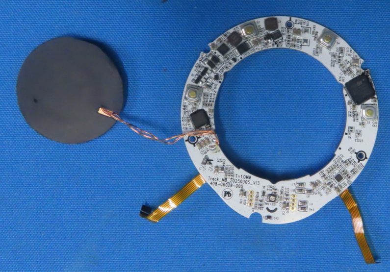
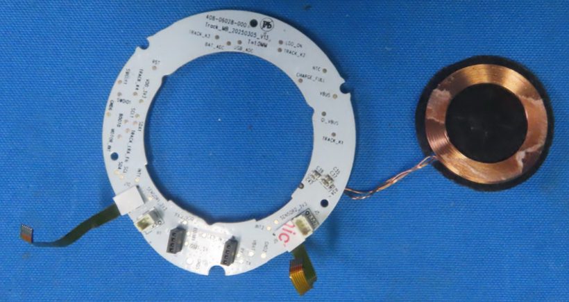
The main board is Track_MB_20250305_V13, part number 408-06028-000, 1.0 mm, stamp 25 15, about
60-66 mm outer diameter with a 40-43 mm opening for the ball (sizes inferred) DOC INFERRED CRL IP7
p44-p461.
| Part | Identity and marking | Evidence |
|---|---|---|
| MCU | ST STM32F411CEU6, marked STM32F / 411CEU6 / GQ26Y17VQ / CHN GQ 443; the modules moved from a Holtek MCU to the STM32F411 in May 2024 |
DOC CRL IP7 p4510 |
| Qi receiver | Maxic MT5705, lot 245303 (a different lot from the Tune and Touch parts) |
DOC CRL IP7 p46 |
| Charger | SG Micro SGM41523 (U8, SGM / 41523DF / S2GPC); no SGM62117 buck-boost was seen on the Track |
DOC |
| Other parts | 16 MHz crystal YC16.0 (Y1, load caps C102, C103); two SL Schottky diodes and one T4 switching diode; a 1.0 uH inductor; larger capacitors at the Qi coil pads (a resonant or filter bank, inferred); unmarked ESD parts; two S1D-marked SOT-23 parts of unknown type; a small unmarked QFN and a leaded IC near S3 |
DOC INFERRED CRL IP7 p45-p46 |
| Buttons | four SMD tactile switches S2-S5 with round brass actuators; net pads TRACK_K1-TRACK_K4 |
DOC CRL IP7 p45-p46 |
| Status LED | a single top-view LED LED1 between two rows of unpopulated plated holes (RGB per marketing, inferred) |
DOC CRL IP7 p45 |
| Connectors | a white 2-way socket M1 for the motor, a white 4-way socket under tape near the sensor pads, and two black 4-position sockets beside GND2/VBAT/RX/TX that take the dock interposer (inferred); two orange FPC tails to the sensor boards |
DOC INFERRED CRL IP7 p44 |
| Net pads | buttons TRACK_K1-K4; charger VBUS, QI_VBUS, NTC, CHARGE_FULL, LDO_ON, BAT_ADC, USB_ADC, VBAT, VDD_3V3; debug SWCLK1, SWDIO1, BOOT0, BOOT?, RST; two sensor buses (SENSOR1_3V3, INT1, SCL, SDA, SCL1, SDA1, SENSOR2_3V3, INT2); haptics TRACK_?RA_EN, MOTOR_IN?; dock RX, TX, USB_5V |
DOC CRL IP7 p44 |
Sensors
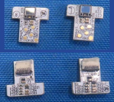
The two sensor boards are T-shaped, SensorL_20241125_V09 and SensorR_20241125_V09 (about 11 x 11 mm),
each carrying one windowed, unmarked sensor package (U9, U11) with SCLK, SDIO and MOTION pads:
an optical motion sensor with a PixArt-style three-wire port is the reading DOC INFERRED CRL IP6
p38-p391. The vendor describes the Track's "two sensors, placed 90 degrees apart"; Batch 1
enlarged the sensor window and changed "sensor positioning to improve vertical-axis rotation for smooth
scrolling"; EVT2 had already repositioned and upgraded the sensors. Two sensors on the ball make twist
(scroll) sensing possible DOC INFERRED111415. Some earlier readings counted four sensor boards
or assumed capacitive sensing; two boards were each photographed front and back DOC.
Motor, ball and dock
- Haptic motor. A flat coin vibration motor about 7-9 mm, unmarked, on red and blue leads to a white
2-pin plug (mates
M1); whether it is an ERM or an LRA is open (the enable net readsTRACK_?RA_EN, whereLRA_ENwould suggest an LRA). Marketing did not advertise Track haptics DOC INFERRED CRL IP6 p411 (details). - Ball assembly. A black hemispherical cup with a central hole and a translucent carrier holding the two sensor boards; the ring opening is about 40 mm DOC INFERRED CRL IP6 p37-p38.
- Pogo board.
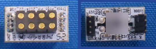
Track_Pogo_Pin_20241122_V08(about 17 x 10 mm), 8 gold domed dock contacts in a 2 x 4 housing labeledGND,VBAT,RX,ON; a separate unnamed interposer board carries headersJ11(GND,RX,TX, one more) andJ4(ON,5V,GND, one more) and aBOOT1pad, and plugs into the main board's two 4-position sockets DOC CRL IP6 p37, p38, p40. Some earlier readings gave the pogo board as..._V00with a 2 x 5 pad array; it is V08 with 2 x 4 DOC. See Module dock. - Qi coil. A multi-strand spiral on black ferrite, a disc of about 34-35 mm (winding about 28 mm outer, 19 mm inner), with a foam ring, unmarked DOC INFERRED.
Battery
The pack is QS801630 1S2P, 3.7 V 600 mAh 2.22 Wh, made of two QS801630 pouch cells of 300 mAh
1.11 Wh each in parallel, bent around the ring under yellow tape, with three wires (red, yellow, black)
to a white 3-way plug; date codes 25H09 (lab photo) and 25G24 (a second photo) DOC CRL IP6 p38; CRL
IP7 p42-p431. The "300 mAh, 1.11 Wh" label seen on its own in the photos belongs to one of
the two pouch cells inside the pack; the Track has no other battery DOC.
Capacity figures disagree: the filed sample has 600 mAh; the website and the 2023 campaign spec sheet said 800 mAh; the v1.1.0 manual says 700 mAh DOC29 (details). See Power and batteries.
Base
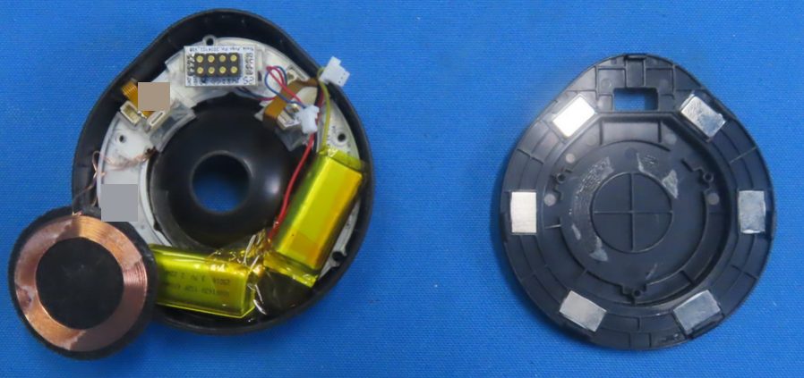
The base is a black teardrop cover with 6 rectangular metal inserts (magnets or steel, not determined),
a window for the contact block and a round seat for the Qi coil; 8 contacts sit in a 2 x 4 recessed block
with two flanking round features. The label carries "Designed in the Netherlands", FCC ID: and IC:
printed with no value, a P/N: NAYA- number whose middle digits are unclear, a serial-number field (value
not reproduced) and Input: 5V⎓500mA; the marks are KC, CE, UKCA, WEEE, VCCI and an N-in-ellipse energy
mark DOC CRL IP6 p37-p381 (details).
As the host sees it
- Dock address.
0x20on the left,0x21on the right MEASURED (owner's board, 3.41.0, 2026-09-03; also nayactl pull requests 2 and 578). - Buttons. The four buttons arrive at the host as mouse buttons with masks 1, 2, 4 and 8 MEASURED (owner's Track, 2026-09-06).
- LED indices. How many LED indices a Track follows is not settled: the board has one LED; an early band test (2026-09-08) that appeared to light 112-126 was later judged a band artifact; a single-index test with a Track has not been done DOC MEASURED (details).
- Ball movement. It arrives as ordinary HID mouse reports: 400 to 1500 reports per movement, deltas up to +/-127 MEASURED (owner's board, 3.41.0, module 2.3.3, 2026-09-03).
- Gesture vocabulary. NayaCore 6.11.0 names for the Track:
horizontal,vertical,rotate;track_up/down/left/right;clockwise_rotateandcounter_clockwise_rotate; for buttons 1-3press,tap,double_tap,hold,tap_hold; for button 4 the same withoutpressSTATIC4. The per-direction names (track_upand so on) are how an older NayaFlow database stored a split axis as separate rows STATIC. - Defaults. The manual: vertical and horizontal = cursor; rotate clockwise = scroll down; counterclockwise = scroll up. NayaFlow's stock profiles "Naya Track Left" and "Naya Track Right": buttons 1-4 tap = mouse buttons 1, 3, 2, 4; holds unbound; rotate = vertical scroll DOC STATIC24.
- NayaFlow behavior. NayaFlow writes a Track button's hold over its tap (a NayaFlow behavior, not a device limit) MEASURED (owner's board, 2026-09). See Module fields.
- Firmware notes. Module 2.1.2 made ball-twist scrolling less easy to trigger; keyboard 3.40.4
(reached stable with 3.41.0) fixed "Track not keeping the Create awake" DOC56. The
v1.0.6 default keymap has a "Toggle Scroll Direction" key (
LA3on Layer 2) DOC3. - Axis locking. Marketing claimed axis locking and "rotate to scroll"; whether axis locking maps to any configuration field is not known DOC17 (details).
Safety
The ball is loose: do not hold the module upside down (manual). The 1S2P pack wraps around the ring; opening the module risks bending or puncturing the cells DOC2.
Open questions
- OPEN The optical sensor part (a PixArt product-ID read on an opened spare Track) (details).
- OPEN Motor ERM or LRA and the small unmarked parts (details).
- OPEN LED index count (details).
- OPEN Base part-number digits (details); base inserts magnet or steel (details).
- OPEN Whether "axis locking" exists in the configuration (details).
- OPEN Retail battery capacity (details).
- OPEN Whether Track Left and Track Right differ physically: NayaFlow ships separate stock profiles and an owner's observation suggests asymmetry; not measured (details).
Sources
-
FCC ID 2BQ4V0825CRL (the module photos are in both halves' filings): exhibits on the FCC record (FCC EAS search, grantee 2BQ4V; mirror fccid.io/2BQ4V0825CRL). Codes are explained on Regulatory records. ↩↩↩↩↩
-
Naya Track User Manual Version 1.1.0 (vendor PDF), p2, p4, p6; see Manuals. ↩↩↩↩↩
-
Naya Create User Manual Version 1.0.6, FCC ID 2BQ4V0825CRR user manual exhibits (fccid.io). ↩
-
NayaFlow 1.25.1: installer default profiles and NayaCore 6.11.0 strings; an older NayaFlow user database (static reading). ↩↩
-
Vendor release notes, NayaTech/NayaFlow-releases (1.14.5). ↩
-
Vendor beta release notes, NayaTech/NayaFlow-beta-releases (1.24.0). ↩
-
nayactl, pull request #2. ↩
-
nayactl, pull request #5. ↩
-
Kickstarter campaign page with its Specs Sheet, naya-create/naya-create (2023). ↩↩
-
Kickstarter update 13, 2024-05-08. ↩
-
Kickstarter update 16, 2024-10-06. ↩
-
Kickstarter update 17, 2024-11-04. ↩
-
Kickstarter update 18, 2025-01-02. ↩
-
Kickstarter update 19, 2025-02-11. ↩
-
Kickstarter update 20, 2025-03-19. ↩↩
-
Reddit, vendor post 13jydnp (2023-05-17); archived text, not live-verified. ↩
-
The vendor's former product pages, archived by the Wayback Machine (naya.tech captures); cited only. ↩